Difference between RigidLink Beam or Bar

Telec
Posts: 30
Joined: Sun Oct 11, 2020 8:27 am

Re: Difference between RigidLink Beam or Bar

Post by Telec » Wed Oct 21, 2020 5:22 pm

Just insert your material parameter assuming that in X you have displacements, and in Y you have force per unit-length instead of just force
ok .. if I understand correctly, I should take my 'fy' of the material and divide it by the distance between the connectors. In this way it would no longer be a value of fy referred to the single connector but distributed on the discretization that stko does automatically?
stko3.PNG
stko3.PNG (4.89 KiB) Viewed 4104 times

STKO Team
Posts: 3066
Joined: Tue Oct 29, 2019 8:45 am

Re: Difference between RigidLink Beam or Bar

Post by STKO Team » Thu Oct 22, 2020 8:15 am

I should take my 'fy' of the material and divide it by the distance between the connectors
Exactly, in this way you have a force per unit length. Note that you have to do the same for the Young's modulus.
Then, if you check the -distributed option in the ZeroLength element, STKO will "transform" your distributed springs into nodal springs, by computing the proper lumping factors (tributary length) based on the mesh size.

How does STKO "transform" your distributed (force per unit length) material into a nodal (force) material? Simply wrapping your original material into a parallel uniaxial material with the proper lumping factor for that node (look into the element.tcl file to see what it does).

Code: Select all

# material parallel generated by zeroLength distributed
uniaxialMaterial Parallel 55 2 -factors 0.19533333333333314
uniaxialMaterial Parallel 56 1 -factors 0.19533333333333314
uniaxialMaterial Parallel 57 1 -factors 0.19533333333333314
uniaxialMaterial Parallel 58 1 -factors 0.19533333333333314
uniaxialMaterial Parallel 59 1 -factors 0.19533333333333314
uniaxialMaterial Parallel 60 1 -factors 0.19533333333333314
element zeroLength 419 36 7 -mat 55 56 57 58 59 60 -dir 1 2 3 4 5 6 -orient 1.0 0.0 0.0 0.0 1.0 0.0
As you can see, with the distributed option, the ZL element takes the parallel material and not the original one. What the parallel material does is:
  • stress = stress(original_material)*factor
  • tangent = tangent(original_material)*factor
if the stress of the original material is a force per unit length, and factor is a (tributary) length, the output will in fact be a force.
As a check, if your mesh size is exactly equal to the connector's spacing, the nodal spring will coincide with what you did manually.

What's the advantage of this?
First, it's much easier to model, you don't have to manually draw a lot of lines and connectors, just 2 lines and 1 (distribtued) interaction between them.
Second, if you need to remesh your model for a more accurate results, the effect of the distributed connectors will be the same in an integral sense.

Telec
Posts: 30
Joined: Sun Oct 11, 2020 8:27 am

Re: Difference between RigidLink Beam or Bar

Post by Telec » Thu Oct 22, 2020 5:06 pm

and instead if I wanted to apply the zl element distributed on a face? I have read that I must have a force per unit area law. But in this case, modeling the top flange of the beam with a shell element

OK thanks so much. I've tried the zl distribuited.

Returning to the constitutive links of the materials recommended to me.
3) Where can I find information on this DamageTC3D material to study it?
https://www.researchgate.net/publicatio ... hear_walls
https://www.researchgate.net/publicatio ... onry_walls
I have seen the research articles. But how can I understand which parameter values ​​to enter in STKO? Are the values ​​below ok for any concrete shell element?
stko4.PNG
stko4.PNG (14.92 KiB) Viewed 4094 times
Also, if I wanted to do only nonlinear static analyzes, does it make sense to consider a model of this type that takes cyclic damage into account? Or could I use another, easier to set up constitutive bond?

STKO Team
Posts: 3066
Joined: Tue Oct 29, 2019 8:45 am

Re: Difference between RigidLink Beam or Bar

Post by STKO Team » Fri Oct 23, 2020 8:32 am

and instead if I wanted to apply the zl element distributed on a face? I have read that I must have a force per unit area law. But in this case, modeling the top flange of the beam with a shell element
Exactly! Both the top-beam-flange and the deck must be faces. So the distributed zerolength that connect them will be per-unit-area.
Also, if I wanted to do only nonlinear static analyzes, does it make sense to consider a model of this type that takes cyclic damage into account? Or could I use another, easier to set up constitutive bond?
The problem is that you don't have so much 3d models for concrete. There is one with less parameters, the PlasticDamageConcrete3d (that in theory is pretty similar to the DamageTC3D) but the input parameters are non-physical and very hard to calibrate.
Instead the DamageTC3D model has more parameters, but they are fairly easy to set-up. The more complicated ones already have default values that should be good for any type of concrete.

In the reference paper you can study in detail the meaning of all those values.

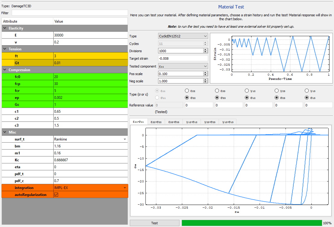
These are good parameters to start with, for a concrete with 30 MPa of compressive strength (values given assuming N/mm^2). As a first approach to this model, change only the Elasticity parameters, and the parameters I highlighted in the picture below. Play with them and use the material tester to see how they influence the response.
Click on each of them to see their description in the text-bot at the bottom of the material editor.
params.jpg
params.jpg (257.71 KiB) Viewed 4094 times

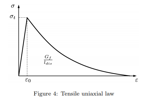
Parameters highlighted in Yellow are for the tensile response
  • ft: tensile strength
  • Gt: tensile fracture energy
ft.png
ft.png (19.36 KiB) Viewed 4094 times

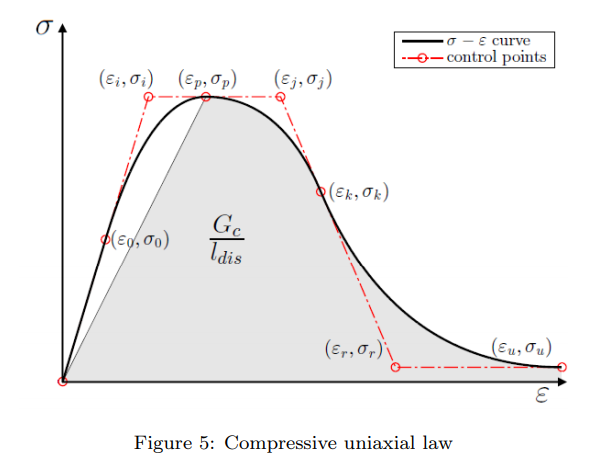
Parameters highlighted in Green are for the compressive response
  • fc0: elastic limit
  • fcp: peak compressive strength
  • fcr: residual strength
  • ep: strain at peak compressive strength
  • Gc: compressive fracture energy
fc.png
fc.png (56.42 KiB) Viewed 4094 times
Parameters in orange are algorithmic parameters. the autoRegularization deals with the topic of fracture-energy-regularization for an objective response with different mesh-sizes (you can read about this in my paper and the references therein)
The integration instead is not given in that paper. The implicit is the default one, the time-step size can be whatever you want, because the solution will be implicit, so it will iterate for covergence. If you use the IMPL-EX (mixed implicit explicit) your problem will (almost) always converge, however the time step should be quite small.

Try with these first informations and let's see if you need more

Telec
Posts: 30
Joined: Sun Oct 11, 2020 8:27 am

Re: Difference between RigidLink Beam or Bar

Post by Telec » Fri Oct 23, 2020 5:00 pm

ok thanks .. I also saw the videos on youtube related to this material. Now it is clearer to me. But a question, how can I calculate the values ​​of Gt and Gf, in case I don't have them from experimental data?

STKO Team
Posts: 3066
Joined: Tue Oct 29, 2019 8:45 am

Re: Difference between RigidLink Beam or Bar

Post by STKO Team » Mon Oct 26, 2020 10:09 am

If you don't have experimental data, you can fomulas given in national codes, for example, for the CEB-FIB Model code:
Immagine 2020-10-26 110434.png
Immagine 2020-10-26 110434.png (3.75 KiB) Viewed 4088 times
These values are real fracture energies (i.e. Work per unit-area... for example if you're using N-mm as your units, N/mm]). You can input them as they are (N/mm) if you use the -autoRegularization option.
Otherwise, you should input them as specific fracture energy (N/mm^2 dividing them by the characteristic length of the finite element).
I suggest you to always use the -autoRegularizaiton, because in that way, it will be OpenSees itself, that will regularize the fracture energy for you.

Telec
Posts: 30
Joined: Sun Oct 11, 2020 8:27 am

Re: Difference between RigidLink Beam or Bar

Post by Telec » Tue Oct 27, 2020 9:52 am

Ok thx. I have found the first eq. (Gt) on the CEB - FIP Model code 2010. But the second (Gc) no. Where can I found it?

Although I tried to use the equation for Gt but I don't get the values ​​that are in the picture
STKO Team wrote:
Fri Oct 23, 2020 8:32 am
params.jpg

STKO Team
Posts: 3066
Joined: Tue Oct 29, 2019 8:45 am

Re: Difference between RigidLink Beam or Bar

Post by STKO Team » Tue Oct 27, 2020 12:11 pm

The one for compressive fracture energy in that equation is simply derived from the Tensile fracture energy (given in the FIP Model Code) and scaled by the square of the ratio of the compressive to the tensile strength.

Post Reply