Page 1 of 2
Infilled frame
Posted: Sat Nov 02, 2024 11:08 am
by giulio.zanellato
Hi, I'm doing a pushover analysis on a RC frame with a fiber reinforced masonry infill. I modeled the infill using a double strut scheme: as you can see the two central nodes (vertice 0 and 1) connect both struts, instead I would like to create the two struts separately thus allowing them to be independent from each other. So I first created the strut from bottom left to top right, hid the newly created strut, and made the strut from top left to bottom right with new vertices in the center. What I see however is that STKO collapses the overlapping vertices into a single vertex "0" and "1", thus constraining the two struts to X. How can I then create two overlapping points, without STKO collapsing them into a single point, to make the two struts independent?
Re: Infilled frame
Posted: Tue Nov 05, 2024 11:01 am
by kesavapraba
Hi, did you try with two vertices created at the center? Each for one strut. When two vertices are at the same location, STKO will ask you to choose either one for creating the strut. By selecting distinct vertices, you can have independent structs.
Re: Infilled frame
Posted: Tue Nov 05, 2024 2:06 pm
by giulio.zanellato
yes I tried to create two different points or vertices in the center, but when I do "make wire" it joins them all and consequently the overlapping vertices implode into a single vertex.
Re: Infilled frame
Posted: Thu Nov 07, 2024 5:05 am
by kesavapraba
Ok, Actually the "wire" command makes one single geometry from those three geometries since the struts are overlapping. Why don't you try separating the struts and apply "rigidLink-beam " connection between the frames and struts?
Re: Infilled frame
Posted: Thu Nov 07, 2024 7:36 am
by STKO Team
You have to create 2 edges without the node in the middle. Even if they cross at center the makewire command will not create an extra node where they cross (what would happen instead with the merge command). The make wire just joins vertices that are overlapping, but will not create extra vertices where two edges cross
Re: Infilled frame
Posted: Thu Nov 07, 2024 2:01 pm
by giulio.zanellato
ok. But if I need to have that node in the center, as the section properties of the element are assigned, how can I do to not have a single node but two independent overlapping ones?
I attach an example image of the strut model.
I need the node in the center because half of the strut is composed of 3 sections: 2 elastic ones with different properties, and a non-linear section with fibers towards the center of the strut.
Re: Infilled frame
Posted: Mon Nov 11, 2024 9:16 am
by STKO Team
Sorry but I don't understand what you are trying to do.
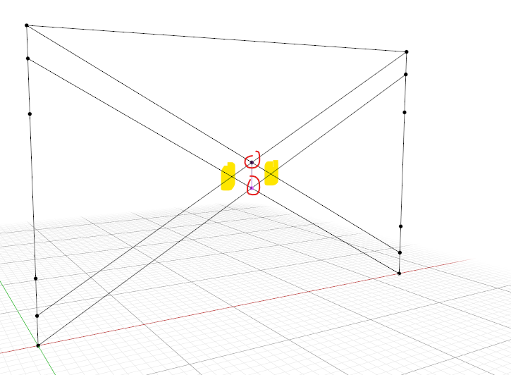
Your initial model is exactly as described in your image: The 2 struts do not have common vertices (see in the yellow highlight zone, that intersection does not have a vertex, thus they are independent)
The only central vertices are the red ones (one for each strut):
- bstrut.png (141.04 KiB) Viewed 839 times
Or am I missing something?
Re: Infilled frame
Posted: Mon Nov 11, 2024 10:09 am
by giulio.zanellato
Sorry, I explained myself badly.
I attach the new images where you can understand better:
in the center of the panel there must be 2 pairs of overlapping nodes (as in the figure), for a total of 4 nodes. For each pair of nodes a double strut is connected: the first double strut starts from the bottom left to the top right, while the second starts from the top left to the bottom right.
Node 1 and 2 belong to double strut 1, while nodes 3 and 4 belong to double strut 2.
So by numbering the nodes from 1 to 4 as shown in the image, node 1 and 3 are overlapped, while node 2 and 4 are overlapped.
In this way the two double struts are completely independent.
I need to have overlapping nodes, otherwise the two double struts can pass through the same pair of nodes and are not independent.
Re: Infilled frame
Posted: Mon Nov 18, 2024 12:47 pm
by STKO Team
Check this:
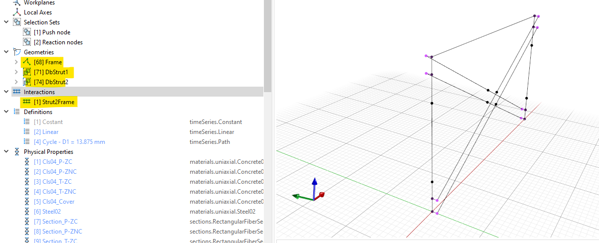
The only option you have is to create 3 geometries.
- Put in a Wire (MakeWire command) all the edges for the frame
- Join all edges of double-truss-1 into a compound (You have 4 edges for each double-strut, first do a makeWire to produce 2 detached edges, then put them into a single geometry with the Make Compound command)
- Do the same for double-truss-2
- Join the frame and the 2 compounds of double-truss using a node-to-node link. In this example I used the vertices of the frame as master and the vertices of the trusses as slave. You can use this interaction with an EqualDOF, attaching the DOFs for which you want continuity
In this file I moved the truss-1 and truss-2 10 units away from the frame just to show you the concept. Also because it's easier in this way to define the interaction. When you are done modeling, you can move them back to their original position
- dbstrut.png (227.05 KiB) Viewed 812 times
Re: Infilled frame
Posted: Tue Nov 19, 2024 12:43 pm
by giulio.zanellato
Ok perfect thanks. I put the equaldof as you told me and now the analysis proceeds.
The only point is that the analysis works exclusively with these Analysis settings (see figure 1) and already having experimental and numerical data to compare the hysteretic cycle with I note that the stiffness of the cycles (initial slope of the hysteretic cycle) is quite estimated, but the resistance reaches a peak of 170000 N when in reality it should reach about 350000 N.
Isn't it that using a Krylov-Newton algorithm loses part of the solution?
I tried to put the equaldof both in dx,dy,dz and in dx,dy,dz,Rx,Ry,Rz but it doesn't change the result in terms of resistance.
The model in terms of resistance of the materials and data entered is correct, but unfortunately I don't get the expected results in terms of resistance.
What could be the problem?